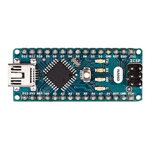
Arduino Nano Pin Layout In this system we have use the Arduino
4.6 (511) · € 28.99 · En Stock

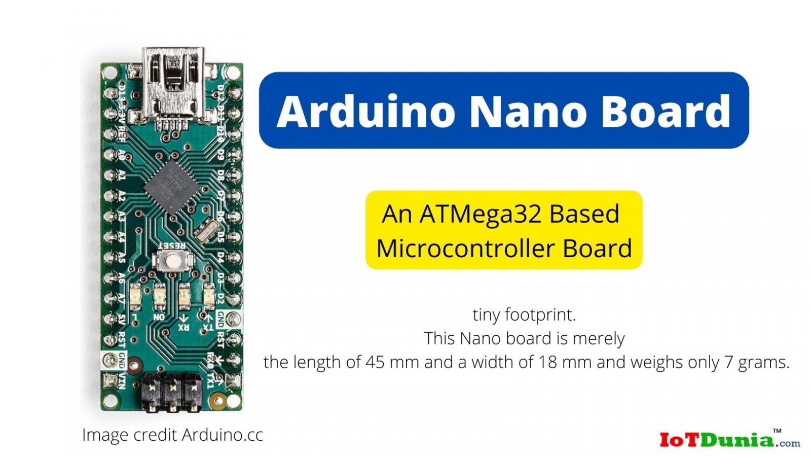
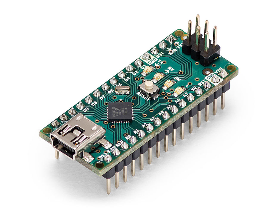
Download scientific diagram | Arduino Nano Pin Layout In this system we have use the Arduino Nano 3.0 which is a 30 pin board having ATMega328 as an microcontroller embed into it. Arduino Nano has 14 digital I/O pins, 8 Analog reference pins and has a clock frequency of 16MHz [18]. As seen from the number of I/O ports it is possible to connect number of sensor nodes to these boards. Arduino Nano can be powered by Mini-B USB and has an operating voltage of 5V. The data gathered by the sensors nodes are being passing on to the base station through serial communication i.e Rx and Tx. The transmission and reception is done by Pin no. 0 and 1. from publication: A low cost environment monitoring system using raspberry Pi and arduino with Zigbee | Emerging environmental related problems have greater impact on technical, scientific, social and economical fields, which is why this issue needs attention. On a global scale this issue are being sort out using satellite based instruments. This paper discusses a monitoring | Raspberry Pi, Zigbee and Arduino | ResearchGate, the professional network for scientists.
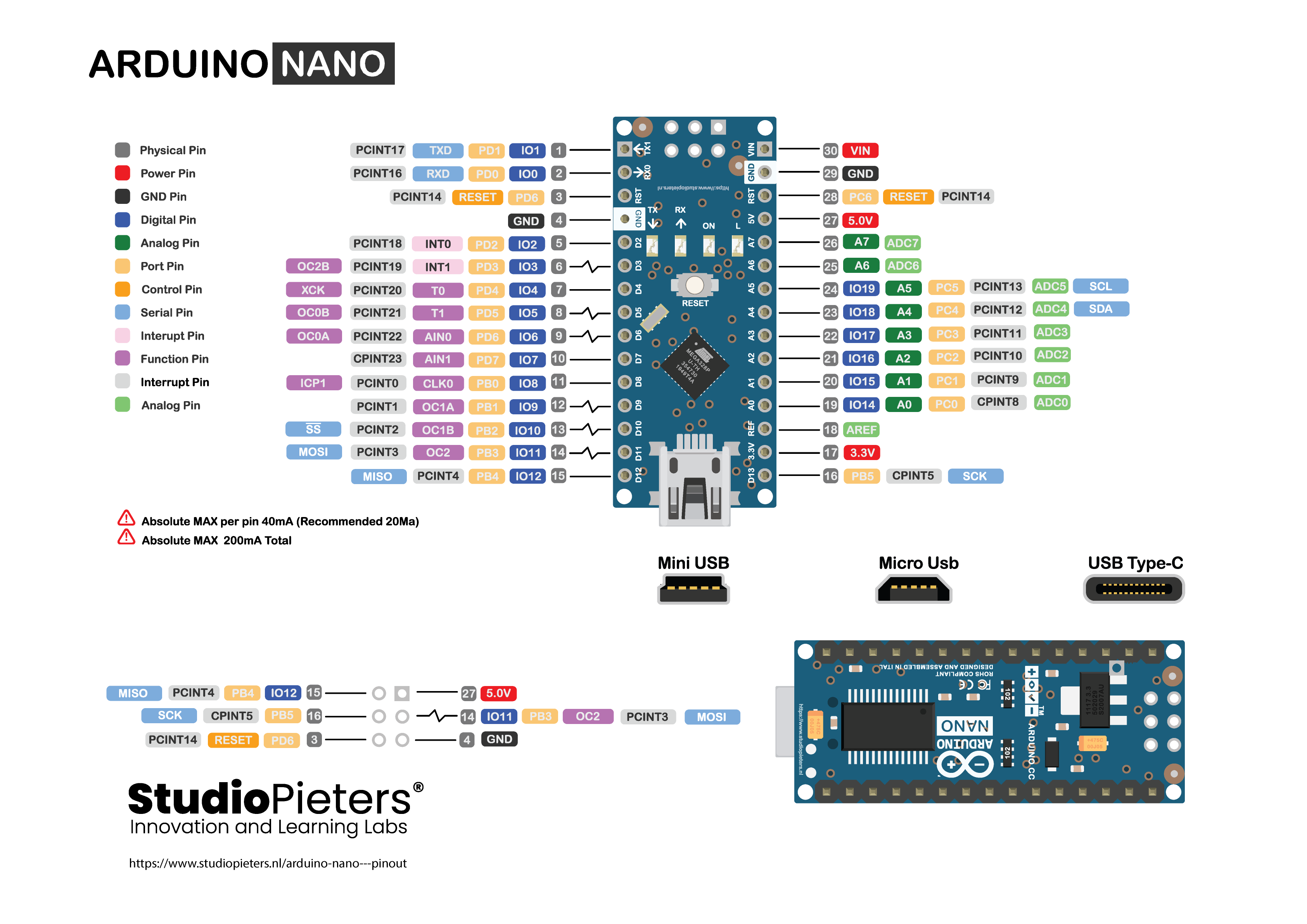
Arduino® Nano - Pinout
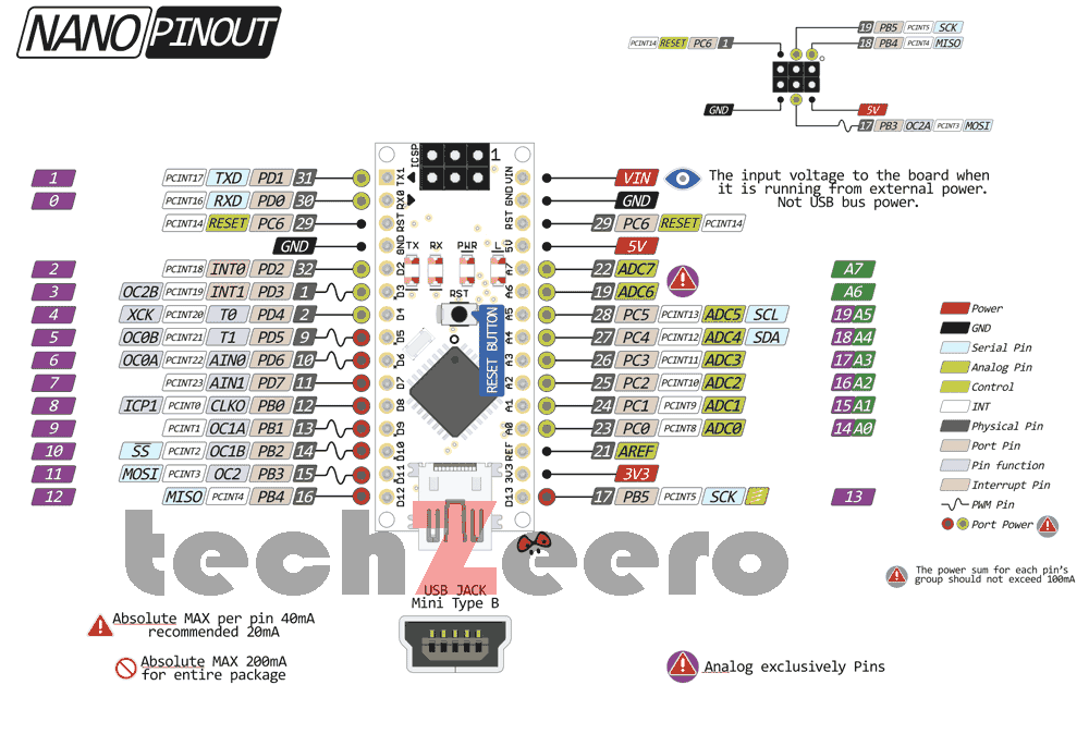
Arduino Nano - Pinout, Specifications, Pin Configuration

ESP32-S3 based Arduino Nano ESP32 board supports Arduino and MicroPython programming - CNX Software
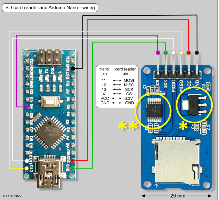
External SD card reader: Arduino Nano, ESP8266 and ESP32 – thesolaruniverse
Arduino Digital Gpio Of Arduino
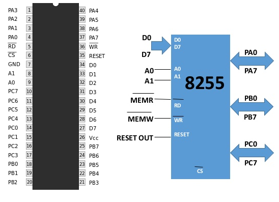
Increasing Digital I/O Pins of Arduino uno Using 8255 Peripheral Programmable Interface with Arduino
What is Arduino Nano Board ? Features, datasheet and Pinout

Low Level Arduino Programming — LED Blink (Part 1), by Sam Munday-Hall
Arduino Nano — Arduino Official Store

Nano Every Arduino Documentation